In this post, I’ll give a basic overview of how we captured the scenes in the last post using Google’s Project Tango Tablet. I’ll also talk about some of the quirks of the Tango and some general tips to get the best results.
If you are a Tango user, you might want to pay special attention to the IR Leakage in Tango Color Images section.
Contents:###
Introduction: Why Tango?
The goal of my research is to try and reason about light propagation in a scene. To do this for a real world scene, we obviously first have to capture the scene. What does it mean to capture the scene? Well, for our purposes, we want to get the geometry and appearance of the scene. More concretely, this translates to a scene mesh and a bunch of linearized radiance maps registered to the scene geometry.
Fortunately for us, the Tango provides the scene geometry and registered (but uncalibrated!) imagery essentially out of the box. The Tango comes with hardware that can get 3D data using structured light, as well as a software API that can perform accurate localization. We can basically treat the device as a black box that gives us image frames, depth frames, and the associated camera poses.
The Tango hardware actually does this much more effectively than other RGBD sensors such as the Microsoft Kinect and the Asus Xtion Pro, even when these are used with state-of-the-art reconstruction methods such as ElasticFusion. The primary reason is that the Tango uses a wide field-of-view, high frame-rate camera for tracking (and a separate camera to capture color imagery). This minimizes the impact of two problems in reconstruction:
- Global registration/loop closure: Imagine a simple panorama scan of a room: you turn in a circle. When you get back to the beginning of the circle, accumulated drift means that your first frame of data might not match up cleanly with your last frame. A wide field-of-view camera makes detecting loop closures much more robust.
- Tracking in featureless regions: In most indoor scenes, there are large regions of wall and ceiling that do not have any features, whether visual or geometric. With the small field-of-view of conventional devices, they fail to localize in such regions. In fact, in most registration papers, you can see their scans only capturing the interesting, desk-heavy areas of offices and stopping suspiciously once they near the ceiling.
So the Tango is a decent device for scanning rooms. How do we do it?
Capture Process
We use a two-pass capture procedure for optimal registration. In the first pass, we use the Project Tango Explorer app to record an Area Description File, or ADF. This is what will provide us with accurate localization in the second data capture pass.
Our second pass uses a different app, similar to the Tango Tricorder, which loads the ADF and then starts saving every image frame and point cloud frame, each with its associated pose.
Since we want a mesh rather than a point cloud, there’s a bit of extra work to do. We first take each point cloud frame on its own and compute the normals at each point. For now, the best method is something similar to PCL’s NormalEstimation that computes normals via nearest neighbors; once the Tango API actually returns a full depth image (XYZij), then normals will be much simpler to extract.
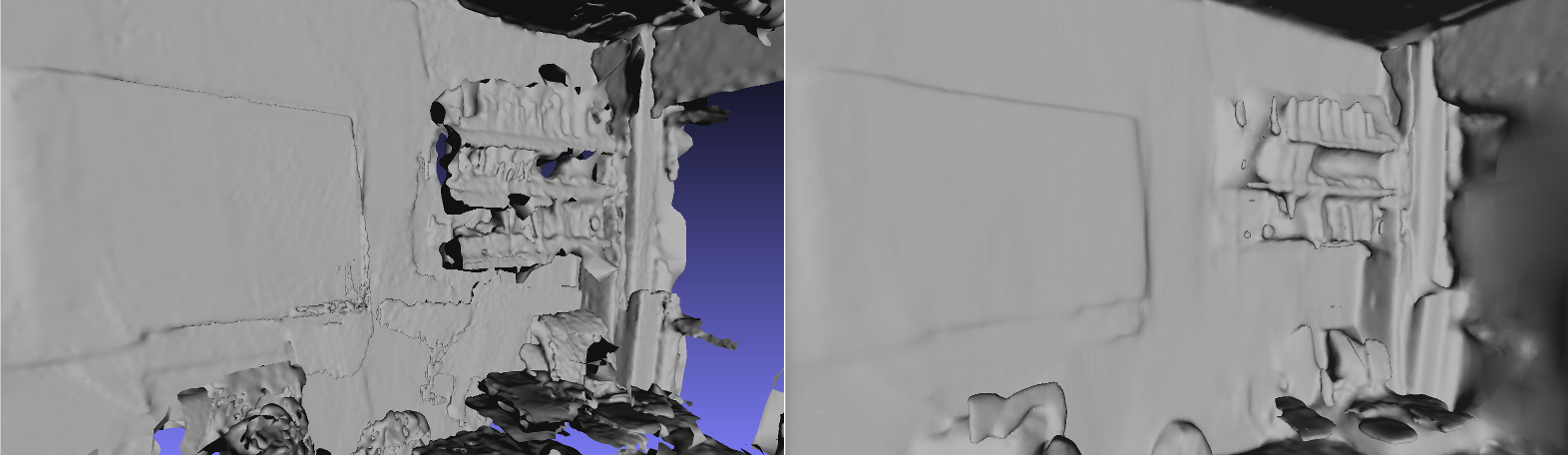
Once we have normals, then it is a simple matter to dump the points into a standard reconstruction algorithm such as Poisson Surface Reconstruction or Floating Scale Surface Reconstruction, or any of the ones built into Meshlab. In our work, we find that Poisson is most appropriate; it handles misregistrations resulting in doubled surfaces more cleanly and it hole-fills windows and lights that blow out the IR sensor.
A little bit of manual cleanup in Meshlab, e.g. deleting a few grossly misregistered regions, can help output quality, but if you scan carefully enough (see tips below) this usually isn’t necessary.
Capture Tips##
Here are a bunch of tips for getting clean reconstructions and imagery with the Tango.
Scene Characteristics
- Avoid black surfaces: The depth sensing system on the camera generally does poorly on these. If you must capture a black surface, try to get as head on a view as possible, and move more slowly so that you can get enough depth information
- Avoid incandescent lights: Described in more detail below
- Avoid large glass windows or mirrors: The depth sensor won’t capture these effectively at all, and it might screw up your tracking.
- Minimize thin surfaces mid-scene, such as tables or chairs: This is mostly to reduce the impact of bad registration on your scene geometry. It is better if any such objects are farther away from the Tango when scanning.
Capture and ADF Tips
- Use an ADF!!!: The only way to get globally consistent poses is by using an ADF. You won’t get any loop closure if you don’t prescan the scene
- Capture a complete ADF: Get all the viewpoints of the scene you will reasonably be covering in a scan.
- Move slowly: Make sure you move slowly to minimize motion blur
- Have enough overlap: Make sure to return to areas of the scene you have already scanned so that the Tango can actually close the loop. Even though the camera has a wide field of view, the more overlap the better.
- Be careful around lights and windows: Move slowly when getting near lights and windows to give autoexposure time to adjust
- Capture surfaces head on, not obliquely: You will get better depth data and the registration will be better.
- Examine data after capture: You might want to go back and rescan sections of the scene that you didn’t capture thoroughly, e.g. if you open up the point cloud and see a hole in the middle of the floor. Also, you will often have color frames that have exposure flashes or capture the structured light pattern from the depth sensor - you probably want to throw these frames out.
IR Leakage in Tango Color Images
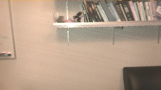
A lot of Tango imagery appears washed out and low contrast. To minimize this effect, stick with daylight and fluorescent lights.
Why does this occur? The answer is infrared light. The Tango tablet uses a single RGBI sensor to capture both depth and color data. Standard RGB sensors, such as those used in webcams or phone cameras, are sensitive to infrared light as well as visible light. Thus, they usually come with an infrared-blocking filter. However, the RGBI sensor in the Tango wouldn’t be able to sense depth if it had such a filter. Thus, what you see is IR bleeding into the RGB channels.
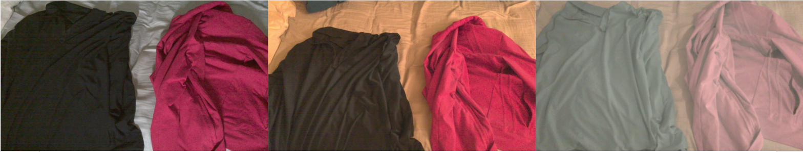
The problem is actually considerably worse: experimentally, the autoexposure functionality on the camera does not seem to function correctly with high amounts of IR. It seems like it autoexposes to the visible light spectrum, but the image then gets blown out with the IR bleeding into the RGB pixels.
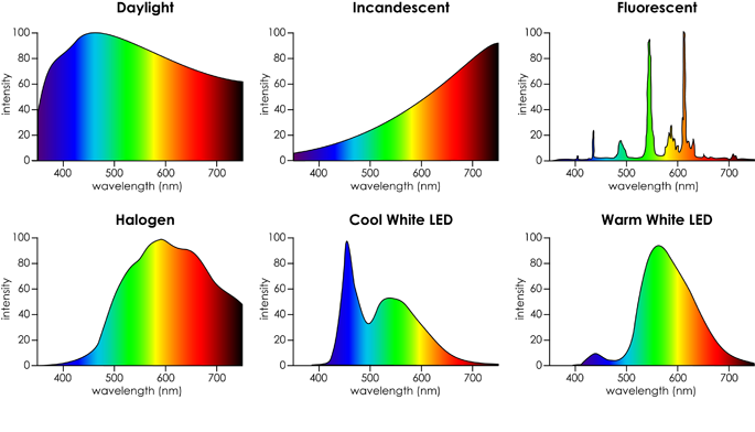
Practically, this means that the best images are obtained with daylight or fluorescent lights, where the power of the light in the IR spectrum is less than the visible spectrum.
The comments in this thread helped lead me on the right path to diagnosing this issue.
Full Workflow
For those interested, here’s a precise list of what our system does (mostly automated after capture). In theory this should let you replicate our results (but there’s probably a lot of hairy coding in there).
Capture
- Capture ADF of scene
- Dump image and point cloud frames of scene, with poses computed post capture (vs. during capture) for more reliable estimates
Depth
- Compute per-frame normals for point clouds via nearest neighbors
- Merge point cloud frames using poses
- Run Screened Poisson Surface Reconstruction at a depth of 8 or 9
- Delete small components (less than 0.1% of the vertices)
- Do a few iterations of Taubin smoothing
HDR Imagery
See the previous post for an explanation of these steps.
- Remove frames showing structured light pattern and grossly overexposed frames
- Resize images down to 640x360, and from now on only process a fraction of the frames (usually less than 1500 frames total) for efficiency.
- Generate edge masks
- Associate non-masked image pixels with mesh vertices. With a high resolution mesh, this means for each image frame, check to see what pixel (if any) a mesh vertex projects onto. Otherwise, just e.g. tracing a ray per pixel and splatting onto nearest vertices might leave holes.
- Solve per-channel bundle adjustment assuming linear camera response with a gamma transform, using L2 norm, on 1/2 or 1/3 of the mesh vertices. First channel uses an initialization of all exposures and all radiances equal to 1; subsequent channels are initialized with the previous solution.
- Apply the per-channel linear exposures to the original input images
Generating Sample Meshes
- Generate a confidence image for each input color image. Generally, we don’t trust oversaturated or undersaturated pixels, so we use a hat function. For an 8-bit value \(x\), our per-channel confidence is \(c = 1 - \frac{|x-128|}{128}\) (carefully chosen so that a saturated pixel has a small but nonzero confidence).
- As step 4 above, associate pixels with nonzero confidence to vertices
- Take a weighted mean or weighted median of all associated pixels to get a single HDR vertex color. The weight we use is proportional to the confidence and the differential form factor between the vertex and the camera pixel. If \(v\) is the vector from the vertex to the camera, \(n\) is the vertex normal, and \(t\) is the camera vector, then the form factor term is \(\frac{-(v\cdot t)(v\cdot n)}{(v\cdot v)^2}\) (ref https://en.wikipedia.org/wiki/View_factor#View_factors_of_differential_areas)