Game engines such as Unity and Unreal Engine, or modelling programs such as Maya and Blender, all involve setting up a 3D scene. During this process, you frequently want to adjust the position, orientation, and size of objects in your scene. The GUIs all include a set of manipulators (AKA widgets, gizmos, tools) that let you control these properties visually, in a WYSIWYG fashion, instead of entering numbers in text boxes.
In 2017 I had to implement some of these manipulators as part of a code rewrite for the Computer Graphics courses at the University of Washington. In the process, I reviewed the manipulators for several common programs (Unity, Unreal Engine, Maya, and Blender) to see how their manipulators worked. This post is a summary of my findings. I’ll separately discuss the Translation, Rotation, and Scale manipulators, describing the visual control itself (what does it look like? what does clicking on each part do?) as well as the actual mapping from mouse movement to transformation. Note that, for Blender, the visual control part is less relevant than the mouse mapping part because of its keyboard-based modal UI paradigm.
Coordinate Spaces
These manipulators are all based around three axes to allow for precise control. Which three axes should these be?
There are two coordinate systems that are commonly used, and one other that is sometimes useful.
- world space
- local or object space
- camera or view space (often implicit)
While you can always swap between coordinate systems, sometimes one makes more sense than another. In Unity and Blender, the coordinate system is explicitly toggled in the UI, whereas Unreal Engine and Maya provide different defaults for different manipulators.
For Translation manipulators, the default should be world space. Usually, translations are used to place objects relative to one another, so it doesn’t make sense for the default to be a particular object’s coordinate space. However, it is sometimes easier to do fine alignments in other spaces; having options for translation is thus very useful. Both Maya and Unreal Engine use world space translations by default.
For Rotation manipulators. the generally correct default is object space. This is because hierarchical articulated models are the standard paradigm for animation. Your finger always bends the same way relative to your palm. For Rotation, Maya adheres to the object-space recommendation, but interestingly Unreal Engine uses world-space for rotations. This likely is to keep objects consistently oriented with respect to gravity, since in Unreal you are more likely to be arranging props in a game world (rather than parts of an articulated model). However, for game worlds you usually won’t rotate around any axis but the up vector, and for this case the two systems are equivalent.
For Scale manipulators, the ideal default is once again object space. Most objects and primitives are modelled naturally around their own coordinate axes with appropriate symmetries. Scaling makes the most sense along these axes, while scaling along other axes skews the shape of the object. In general, arbitrarily changing the proportions (i.e. nonuniform scaling) fundamentally changes the shape of an object, while uniform scaling preserves it. For this reason, in standard scene hierarchies, almost all scales should be uniform (and therefore independent of coordinate system). Nonuniform scales should only be applied to leaf nodes of scene hierarchies, containing primitive shapes.
Translation
Translation Manipulator
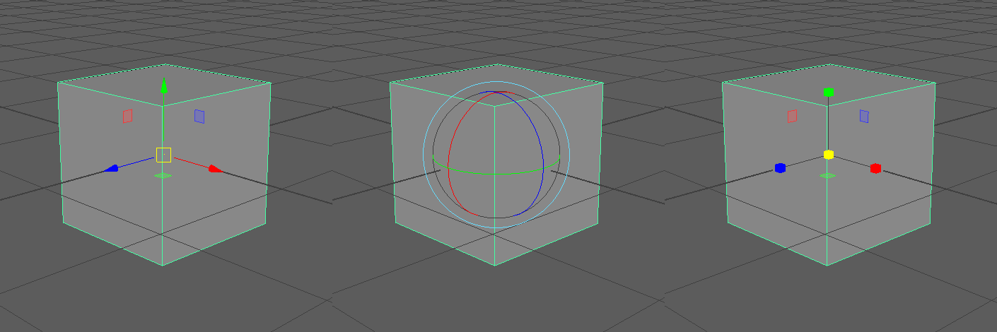
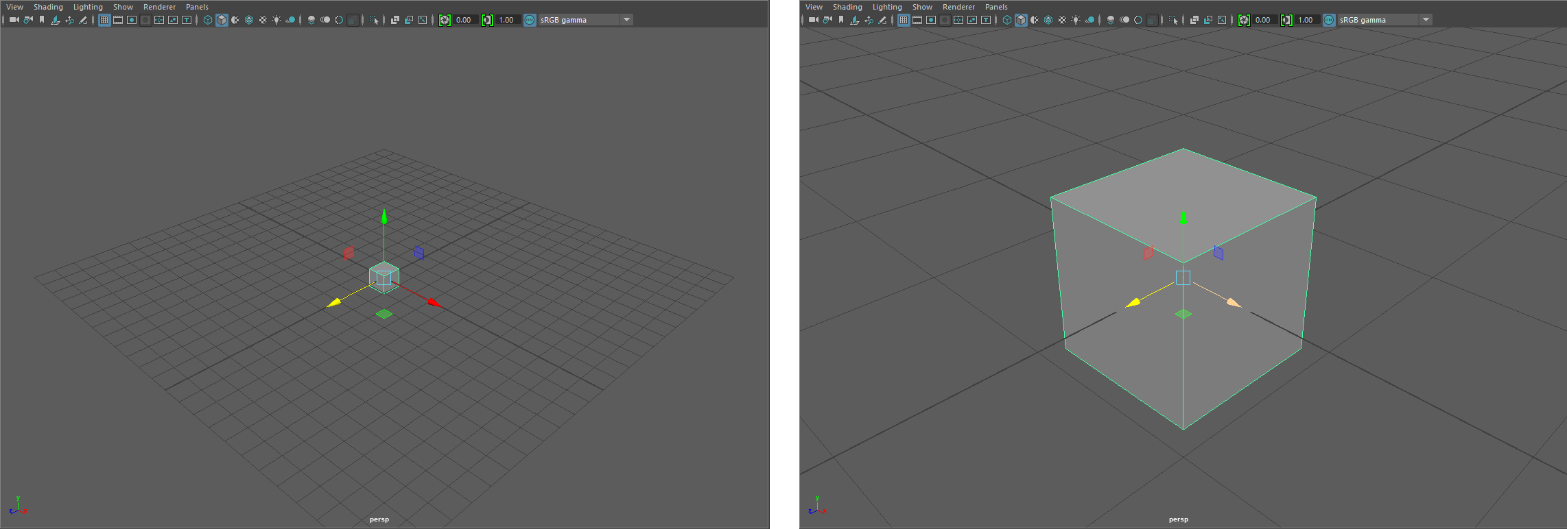
All translation widgets consist of three perpendicular arrows aligned with the coordinate system - the standard way of rendering coordinate axes. Dragging these arrows moves the object only along the specified axis. Most translation manipulators also let you do translation along the coordinate planes. (out of the four I evaluated, only Blender did not). The widget usually shows three small squares on the coordinate planes to control this.
Finally, all manipulators let you translate parallel to the screen plane (an implicit use of view space, since the displayed axes aren’t aligned with view space). In Unity, this is hidden behind a shift-click, while the other programs let you click on the center of the manipulator to do this.
|
|
|
|
Translation Mouse Mappings
What is the most intuitive way to map mouse movements to transformations? A good rule of thumb is to keep the same point under the mouse cursor during a click-and-drag action. Alternatively, the mouse cursor can be hidden during manipulation (as in Blender, for example).
How do we translate this rule of thumb into practice? It is easiest to reason about view-space translations (i.e. parallel to the screen plane). The origin of the manipulator (usually the origin of the object under manipulation) defines a 3D point, while the view direction defines a vector. Together, this point and vector define a plane parallel to the screen going through the origin of the manipulator. When you begin a click and drag action, your initial click location is mapped to a 3D point by casting a ray from the camera center through the mouse position and intersecting it with this plane. As you move your mouse around, the updated mouse position is continually projected onto the plane; the vector from the original click location in 3D space to the current projected mouse location in 3D space is the translation. For manipulators that allow view-space translation by clicking somewhere other than the manipulator origin, the parallel plane is usually defined by the intersection point between the mouse ray and the manipulated object.

Double-axis translations are similar. Project the mouse position onto the plane (with normal defined by the clicked widget component, rather than the view direction) by constructing the ray through the camera center and intersecting it with the plane, then take the difference between the intersection and the originally clicked point to be the translation.

For single-axis translations, the 3D axis of translation determines a 2D line on the screen. We don’t want to force the user to keep their mouse on this line, so we find the closest point on the line to compute the translation. In 3D this means finding the closest point to the camera ray through the mouse position that lies on the axis of translation. This involves a bit of geometry, using the fact that the segment representing the shortest distance between two lines is perpendicular to both lines. A reference can be found in Distance between Lines. Once we’ve computed the closest point to the camera ray on the axis of translation, we set the translation to be the vector between this point and the originally clicked 3D point. (Observation: Unity doesn’t follow this “keep things under the mouse cursor” method for single-axis translations - it uses some kind of fixed scale)

For single-axis and double-axis translations, you can run into some difficulties when an axis of translation is nearly perpendicular to the screen plane. In this case, small mouse movements can result in extremely large translations, which can grow to be infinite near vanishing points. The simplest solution is to bound the scene size; alternatively, you can hide the problematic axes and planes of the manipulator when an axis gets too close to perpendicular to the view plane.
Rotation
Rotation Manipulator
Rotation manipulators usually consist of a sphere with great circles on the surface aligned with the coordinate axes, along with an extra circle around the outside of the sphere. In Unreal Engine, only a quarter of each great circle is shown.
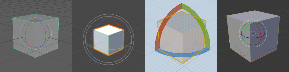
Clicking and dragging on the axis-aligned circles rotates the object around the appropriate axis (such that, visually, the great circle remains in the same spot). However the precise mapping of mouse motion to rotation is different for every system. This is discussed further below.
Clicking and dragging on the exterior circle rotates around to the camera view axis (another implicit view-space transformation).
|
|
Unity and Maya also allow free, two-degree-of-freedom rotation, similar to the classic trackball camera control. This happens when the user clicks and drags on the sphere (but not on the circles). We won’t discuss how trackball rotations work here, but there are plenty of resources on how to implement trackballs (e.g. khronos wiki) as well as alternate free rotation paradigms (e.g. here).
View-Space Rotation Mouse Mappings
We’ll start by looking at view-space mouse mappings, since there is a logical way to perform the mapping. By following our “keep things under the cursor” rule of thumb, assuming we keep the mouse on the ring, we can just take the angle formed by the start cursor position, the center of rotation, and the end cursor position as the angle of rotation.

What happens if our mouse escapes the ring? Similar to our single-axis translation mapping, we’ll just find the closest point on the ring to the mouse cursor location and proceed as before. Intuitively, you can imagine mounting our model onto a Lazy Susan or vinyl record, so that clicking and dragging is just like putting a finger down and manually spinning a disc.
Single-Axis Rotation Mouse Mappings
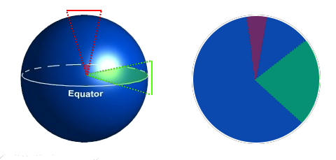
Can we continue to use this record-spinning physical analogy for all single-axis rotations? It’s not disastrous, but there are some peculiarities that we start running into when the axis of rotation is almost perpendicular to the view direction.
- The near side of the ring begins to overlap the far side of the ring in screen space, so when the axis of rotation is exactly perpendicular to the view direction there is an ambiguity as to what position on the ring we are clicking (or what position is the closest to the mouse location). You could just assume that you are clicking on the front side, but then you cannot rotate the object more than 180 degrees in a single mouse movement since you can’t wrap your mouse around to the back side. Maya exhibits this behavior this for single-axis rotations if your mouse remains inside the manipulator.

- If we continue using the nearest point on the ring to determine the rotation (to keep the same point under the cursor), mouse motions won’t map evenly to rotation amounts (Maya does this for single-axis rotations if your mouse location is outside the manipulator).
- If we use a circle in screen-space, instead of the ellipse formed by the projected ring, then we lose the ability to keep the same point under the cursor during rotation. Blender does this for all rotations.
The game engines (Unity and Unreal Engine) instead use a different physically-motivated paradigm, which (approximately) obeys the “keep things under the cursor” rule of thumb when mouse movements remain inside the manipulator, but extend more naturally to movements beyond the manipulator. The physical analogy is a single roller in a roller conveyor (used at airport security or at grocery stores); to spin one of these, you run your finger across the roller. If your fingers were very long, you could spin a single roller by a lot in a single motion by touching the roller with the base of your finger and then gliding the entire length of your finger over the roller.

In this analogy, your mouse cursor is the spot on your finger that first touched the roller, and your 3D object is attached to the center of the roller. Even if your cursor leaves the roller itself, the rest of your imaginary long finger can continue to spin the roller.
In terms of mouse mappings, we first construct the line corresponding to the axis of rotation and project it into 2D screen space. Then, the rotation amount is just the perpendicular distance travelled by the mouse cursor relative to this line, with some scale factor.

What scale factor should be used? There are a few options:
- To respect the “keep things under the cursor” rule, at least approximately, we could choose a scale such that the diameter of the manipulator maps to 180 degrees. This doesn’t quite line things up visually for mouse movements near the edges of the manipulator, but ensures that a 180 degree rotation from one side of the manipulator to the other keeps the same spot under the cursor.
- Another option, inspired by the roller analogy, might be to map a 360 degree rotation to the circumference of the manipulator, although this choice results in less visual correspondence.
- In Unreal Engine, the mouse cursor is hidden, so the scale factor doesn’t have to necessarily match some visual measurement. Instead, you can just choose some approximate range such that a comfortable range of mouse movement maps to the complete range of possible rotations.
- In general, this factor can be chosen for the application - if you need to precisely specify small rotations, then you can use a smaller scale factor, but if you need to be able to specify large rotations, then a larger scale factor is necessary.
In my implementation, I chose to stick with the roller analogy by default, unless the axis of rotation was less than about 20 degrees from the view axis, in which case we switched over to the record analogy.
Scale
Scale Manipulator
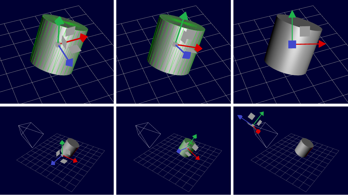
The scale manipulator looks a lot like the translation manipulator, with cubes instead of cones as the arrowheads. Dragging on the cubes scales only along the corresponding axis, while dragging on the center does a uniform scaling on all three axes.
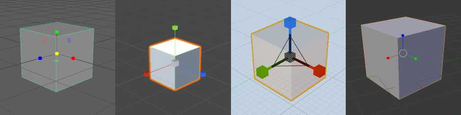
Unreal Engine and Maya also allow you to uniformly scale along two axes; in Maya these are the same squares as the translation widget, while Unreal Engine has small triangles at the corners where the coordinate axes meet. Maya’s double-axis scaling isn’t a free, two degree-of-freedom scaling - it uniformly scales along the two axes.
Scale Mouse Mappings
Mapping mouse movement to a uniform scale is extremely simple. Most manipulators just pick a direction in screen space and map movement along that axis to scale. For example, in Maya, you drag right to make things bigger and left to make things smaller (up/down for Unreal, upper-right/lower-left for Unity). The precise conversion factor from pixels to scale is a matter of choice. One place to start would be to pick a minimum scale (which can be 0) and set the mapping such that dragging all the way to e.g. the left side of the screen in Maya gets you exactly to this minimum scale. The scale mapping does not need to be linear; you often want a bit more precision near the original size (i.e. for scales close to 1), but still allow larger scales at the extremes.

Blender instead uses distance from the object origin, so as you drag away from the object origin from your mouse click point your object gets bigger, and as you drag towards the object origin your object gets smaller. This is definitely the most intuitive mapping, although it means that when downscaling you have to make sure you start your drag action far enough away from the object origin.
Single- and double-axis scaling works very similarly to single- and double-axis translation in the way that a mouse position corresponds to a 3D point. Then, instead of subtracting the originally clicked 3D point, we divide the distances to the manipulator origin to get the new scale. Note that for single- and double-axis scaling, animating the manipulator itself is a little bit more subtle than for translation and rotation manipulators (for which you just apply the computed translation/rotation to the manipulator). For scale, you don’t want to scale the arrowheads (cubes) for the axes you aren’t scaling, so usually we change the length of the axis arrow shafts while keeping the heads the same size.
Other Visual Perks
- Red, Green, and Blue correspond to the X, Y, and Z axes, respectively.
- While dragging, have irrelevant parts of the manipulator (i.e. the axes that weren’t clicked) fade out and highlight the one that was clicked. All the programs except Unity do this.

- It’s useful to indicate how much your current mouse drag has affected the object relative to its starting state. This could be done by showing a ghost version of the original object itself, but it’s more common to show a less obstrusive indicator (e.g. for rotations, shade in a slice of the circle, or for translations, just showing a dot at the mouse down position).

- In Blender the entire line corresponding to the axis being manipulated is shown, while the other axes (and the original widget) are completely hidden.
- Making the mouse cursor disappear can hide some peculiarities in mapping (e.g. single-axis translations that go off of the line). Unreal likes to do this.
- Unity directly manipulates the cursor position to allow for unbounded amounts of rotation: if your cursor goes off the edge of the screen, it will reappear at the opposite side. Without this, you’d have to stop at the edge of the screen, then reclick the manipulator and to continue rotating.
- Snapping can greatly help alignment. Unreal snaps everything by default.
- Make sure that the manipulators aren’t occluded by your scene! Either have manipulators drawn on top of geometry, or have some sort of transparency.
- One subtle but important feature is that the size of the manipulators in screen space is constant. This means that you don’t need to zoom into or out of the scene before you can easily click on the manipulator. In practice this means to multiply the scale of the manipulator by its distance from the camera (from similar triangles).
Closing Thoughts
In general, there is one “correct” way to do translation and scaling, based on the core concept of “Keep things under the mouse”. Most programs do this well, although surprisingly there are still some mistakes that are made. However every program made different design choices for how rotation would work, and there isn’t a clear right way to do it.
On a different note, using nontradional (i.e. non-mouse) 6 degree-of-freedom controllers makes doing translation and rotation much, much easier. I’ve done several projects centered around natural UIs for 3D modelling, and directly comparing even prototype experiences with the mouse-and-keyboard standard manipulators shows a huge difference in intuitiveness and comfort.
Recently, game engines have taken advantage of the Oculus Rift and HTC Vive hand controllers to make VR editing modes (Unreal Engine VR Editor, Unity EditorVR, Sixense MakeVR), which is really exciting and bodes well for the future of 3D modelling.